Arduino ESP32 Electronic Tennis Ball Project
I took a lot of heat over this project from my friends and family.
I get it. It's a lot easier to just hang an ol' tennis ball to hit your windshield letting you know your auto is in far enough so the garage door can close and not hit your auto. That works - I've done it myself.
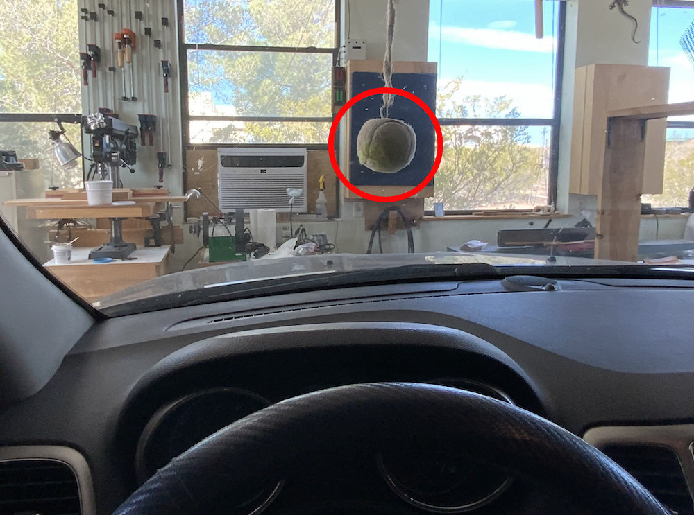
But Maker's don't care about stuff like that. We want something cooler than that so we go out and do it. Right? And besides, who wants a lousy tennis ball hanging in our way when we have work to do in our garage?
That said - here is the basic concept of what I wanted: In very broad terms, I wanted an LED to let me know my auto was well enough in the garage so that the garage door could close and not hit the back of my auto. The details are another story.
The Details
The first question I had was how was I going to trigger the app to know the garage door had been opened? Should I hack the garage opener code and use that? I felt that there was a better (easier!) way to do this, but what? After some thought I remembered that the garage opener had a light that lit up when the door opened (or closed). Voila! That was the key!
So now I had my trigger and I could begin to focus on the rest of the app's concept, which is as follows:
- The garage door opens and its light turns ON and;
- The ESP32 MCU wakes up (from Deep Sleep);
- The green LED begins blinking;
- As the auto continues in it enters the 'red zone' - the green LED turns OFF and the red LED begins blinking;
- The auto is now well enough in the garage so the garage door can be safely closed;
- After a certain amount of time (90 second's in my case) -
- The red LED stops blinking and
- The ESP32 MCU reverts back into Deep Sleep
- The ESP32 is now waiting for the next 'wake up' (light ON) event
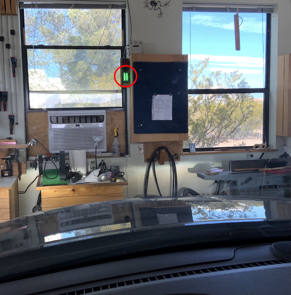
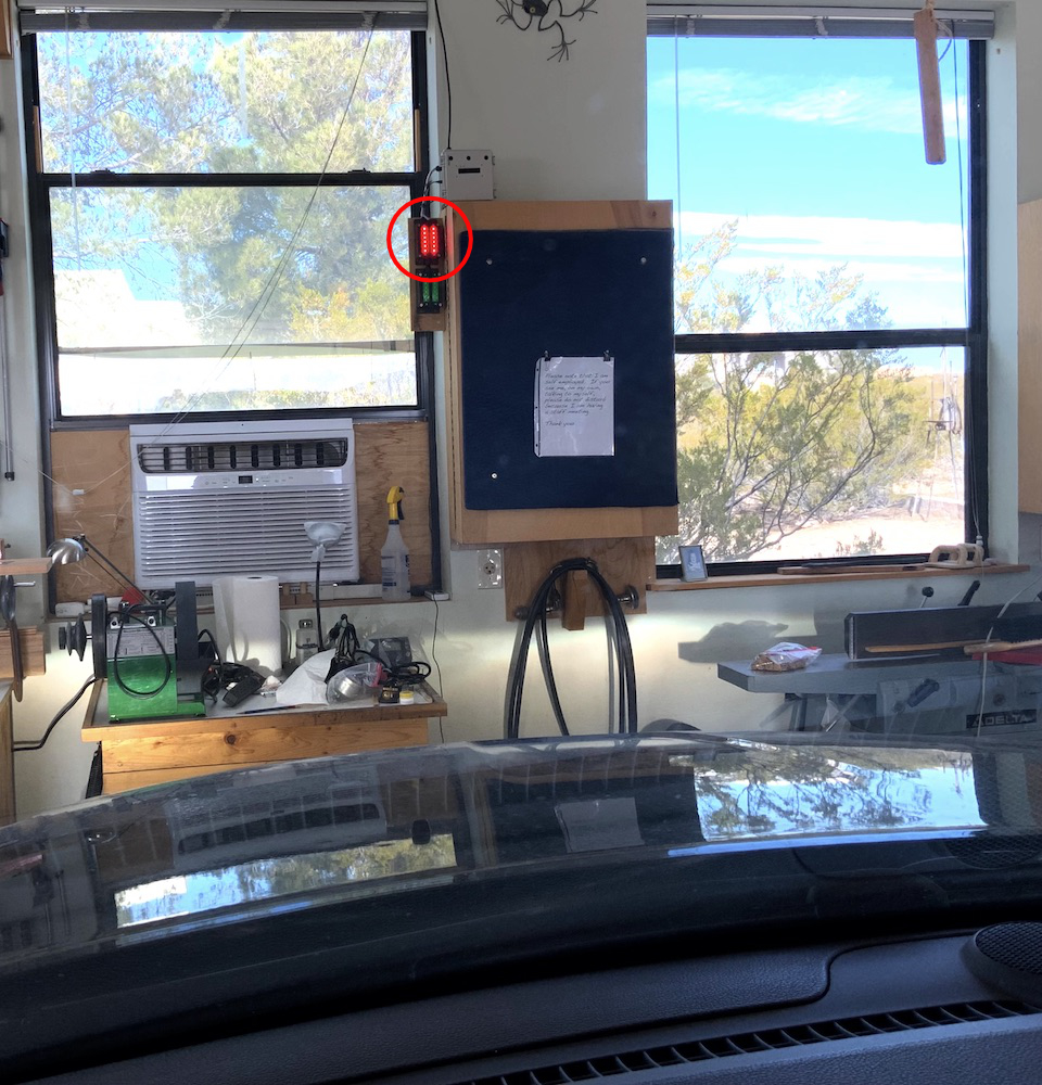
Red Zone
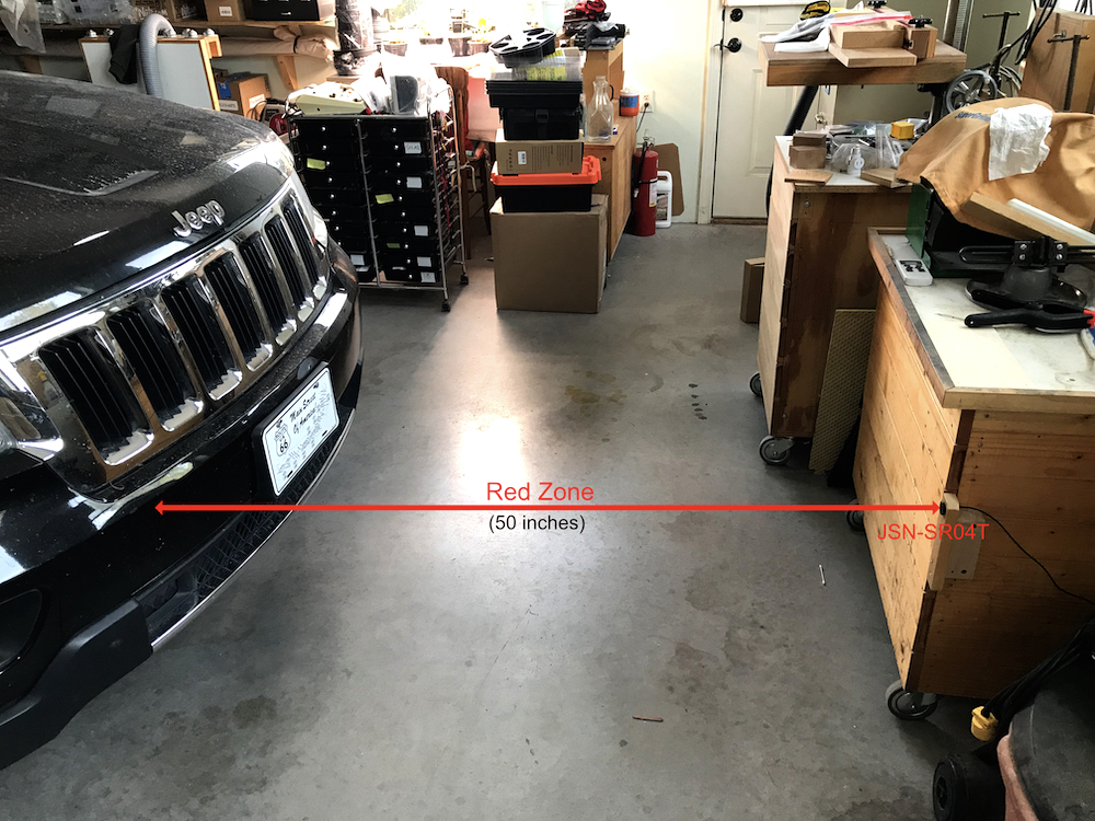
The 'red zone' is the coded distance that, when breached, will turn ON the red LED signifying that the auto is well enough in the garage so the garage door can be closed and not hit the back of the auto. As seen next, 50 inches is my coded distance setting from sensor to auto bumper.
About Those Blinking LED;s
Blinking is totally optional.
Not to split hair's, but IMO if your garage is shorter in length than mine is then you may want to just have the LED's light up and avoid the blinking altogether.
Switching from the 'green mode' to the 'red mode' does take time (msec's). A few things to keep in mind are:
- The length of your garage as noted above and
- How fast you drive into your garage.
I drive into my garage quite slowly. So when I breach the red-zone I will not be too far into the red-zone before the red LED begins blinking (in my case). The red LED lighting up only signifies that your garage door can be closed and not hit your auto. I prefer to just barely breach the red zone so I will have plenty of room in front of my auto. This enables me to sometimes work in my shop without having to remove the auto.
Garage Door Light Setting
My garage door opener is made by Chamberlain. The door control allows me to adjust the length of time that the light stays on. I set it to 90 seconds.
Hardware
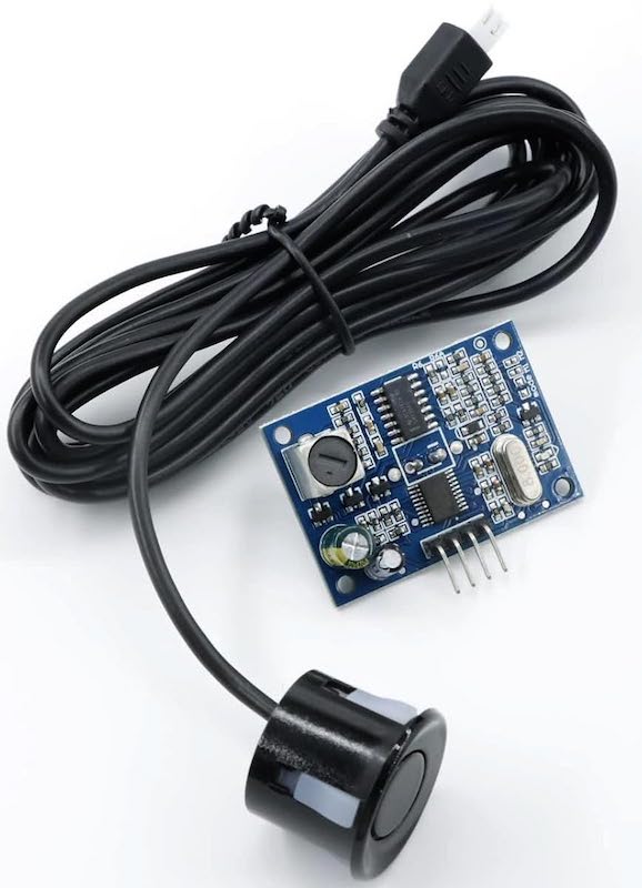
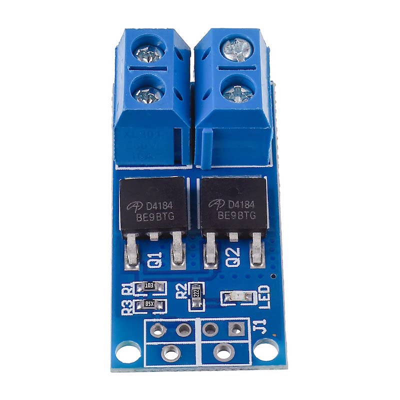
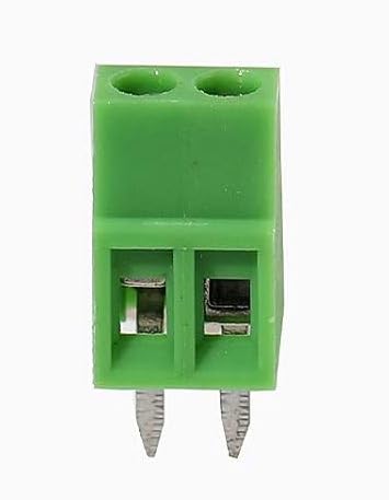
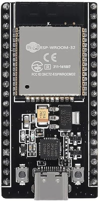
Here is all the hardware used for this project.
Hovering over any image and selecting it will link you to a vendor of that item.
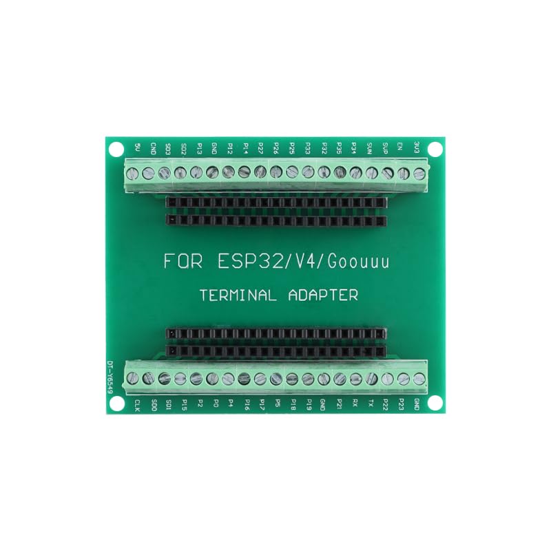
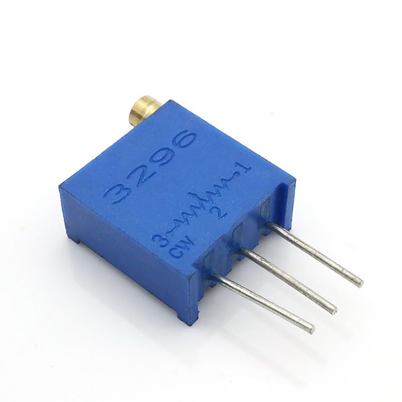
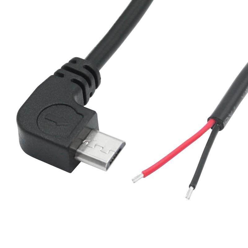
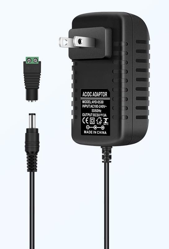
Hardware Comments
Project Schematic
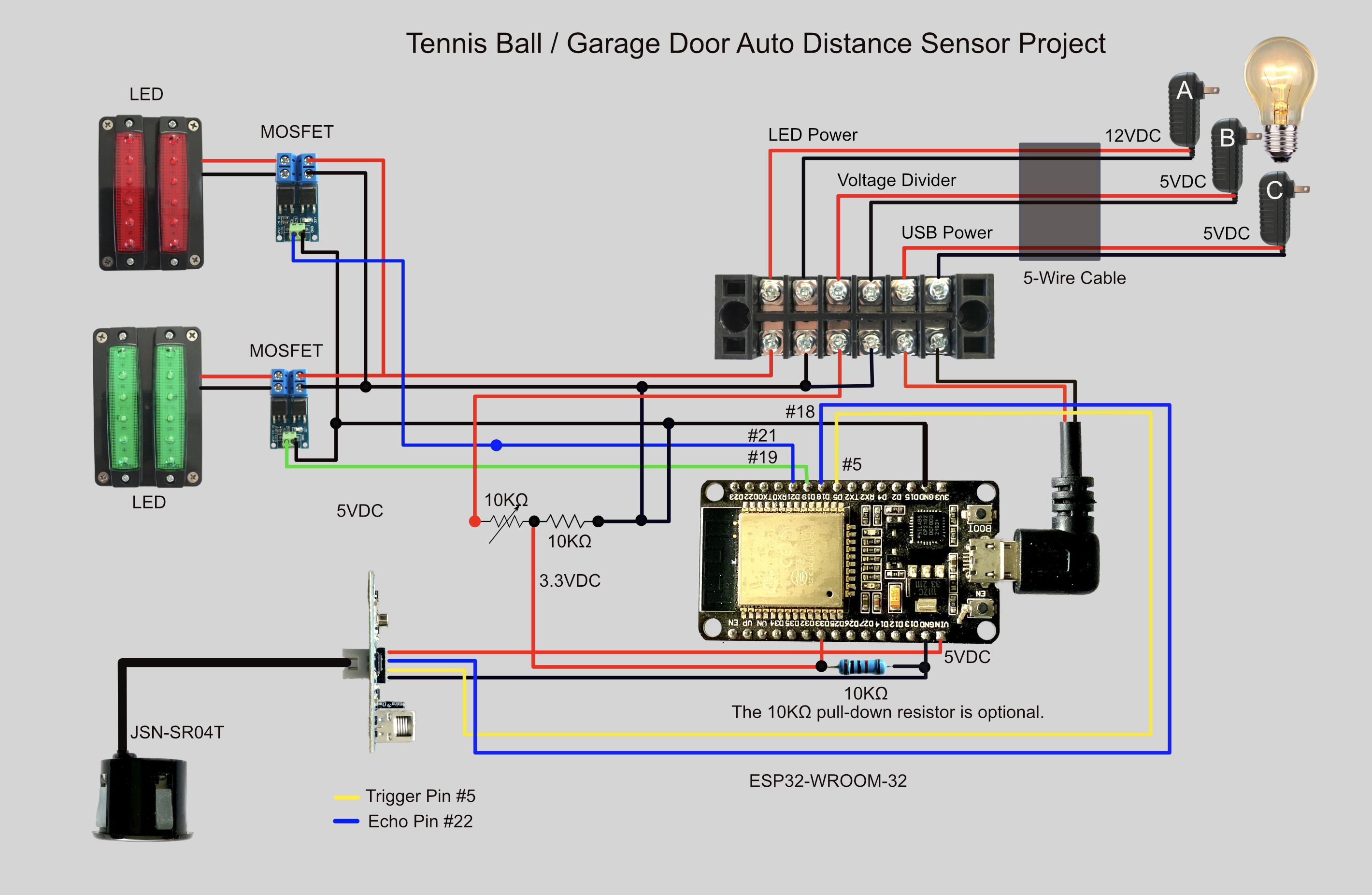
Here is the schematic for this project.
Enclosure Interior
The following image shows the interior of the enclosure.
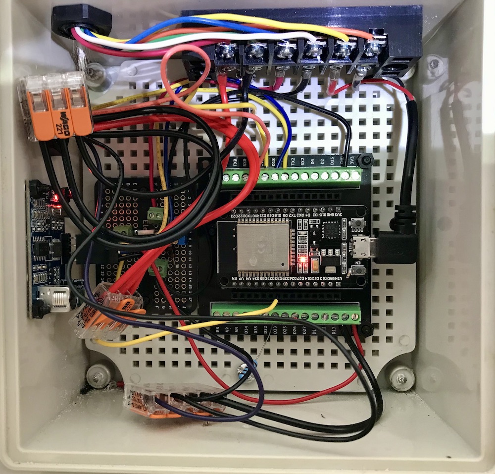
This image shows the interior of the enclosure. It also shows how beneficial the USB right-angle pigtail is. Just to the left of the ESP32 microcontroller is a small perfboard. The voltage-divider is soldered to this board. I also used an external 10KΩ PULL-DOWN resistor to make certain that GPIO#33 was LOW. The C++ project code utilizes the built-in
pinMode(triggerPin, INPUT_PULLDOWN);
code, so the hard-wired enclosure resistor is redundant. However, this redundancy gives me peace-of-mind because if this GPIO pin were ever in a floating or HIGH logic state, the EXP32 would never wake up from its DEEP SLEEP state. That would never work. This reistor can barely be seen beneath the ESP32, but if you look closely you will see it over the silver screw.
Common-ground Note. It is important that this project has a common-ground. If you look at the schematic above, you will see that the voltage-divider negative side is connected to both the enclosure and power supplies ground.
#include "driver/rtc_io.h"

#define BUTTON_PIN_BITMASK(GPIO) (1ULL << GPIO)  // 2 ^ GPIO_NUMBER in hex
#define USE_EXT0_WAKEUP          1               // 1 = EXT0 wakeup, 0 = EXT1 wakeup
#define WAKEUP_GPIO              GPIO_NUM_33     // Only RTC IO are allowed - ESP32 Pin example
RTC_DATA_ATTR int bootCount = 0;


//  JSN-SR04T setup code ........................
const uint8_t trigPin = 5;
const uint8_t echoPin = 18;

const float SOUND_SPEED = 0.034;
const float CM_TO_INCH = 0.393701;  // converts centimeters to inches ...
const int trigger_distance = 50;    // Red Zone distance ...

float distanceCm, duration;
int distanceInch = 0;

//  configure the LED GPIO pins ...........
const uint8_t red_ledPin = 21;
const uint8_t grn_ledPin = 19;

// NEW 8 JUL 2026 used for duration timing of LED's ...
unsigned long startTime;
unsigned long ledDuration;

bool reading = false;
const uint8_t triggerPin = 33;


void setup() {
  Serial.begin(115200);
  delay(1000);  //Take some time to open up the Serial Monitor

// Set mode for US sensor GPIO's ...
    pinMode(trigPin, OUTPUT);
    pinMode(echoPin, INPUT);

    pinMode(triggerPin, INPUT_PULLDOWN);  // PULL-DOWN GPIO#33 ......

// set the RED/GREEN LED group pin modes ...
    pinMode(red_ledPin, OUTPUT);
      digitalWrite(red_ledPin, LOW);
    pinMode(grn_ledPin, OUTPUT);
      digitalWrite(grn_ledPin, LOW);
}


void loop() {

//  JSN-SR04T setup code ........................
  digitalWrite(trigPin, LOW);
  delayMicroseconds(2);       // set trigPin low for 2usec

// Sets the trigPin on HIGH state for 20 micro seconds
  digitalWrite(trigPin, HIGH);
  delayMicroseconds(20);

  digitalWrite(trigPin, LOW);

// Reads the echoPin, returns the sound wave travel time in microseconds
  duration = pulseIn(echoPin, HIGH);

// Calculate the distance
  distanceCm = duration * SOUND_SPEED / 2;

// Convert cm to inches
  distanceInch = distanceCm * CM_TO_INCH;

 Serial.print("\nDistance in inches = ");
 Serial.print(distanceInch);
 Serial.println("\n");

// Delay before repeating measurement ...
  delay(100);
//  end of JSN-SR04T setup code ........................

    esp_sleep_enable_ext0_wakeup(WAKEUP_GPIO, 1);  //1 = High, 0 = Low
    // Configure pullup/downs via RTCIO to tie wakeup pins to inactive level during deepsleep.
    // EXT0 resides in the same power domain (RTC_PERIPH) as the RTC IO pullup/downs.
    // No need to keep that power domain explicitly, unlike EXT1.
    rtc_gpio_pullup_dis(WAKEUP_GPIO);
    rtc_gpio_pulldown_en(WAKEUP_GPIO);

    reading = digitalRead(triggerPin);   // was '33' read logic status of GPIO_NUM_33 digital pin ...

   if (reading == false) // Light is OFF so put/keep MCU to sleep until HIGH event = light turns ON.
      {
      // Serial.println("\n\tGoing to sleep now ... waiting for HIGH Event ...\n");
      Serial.println("Going to SLEEP NOW\n"); //Go to sleep now
      esp_deep_sleep_start(); // MCU is now going to sleep ...
      Serial.println("This will never be printed"); // because mcu is asleep ...
      }
    else if (reading == true) // Light=ON triggered the MCU's GPIO_NUM_33 to an ON or HIGH STATE .........
      {
        if (distanceInch > trigger_distance)  // RED ZONE is vacant - no auto in garage
          {
            digitalWrite(red_ledPin, LOW);
            digitalWrite(grn_ledPin, HIGH);
            ledBlinkOn(19, 20000);
            ledBlinkOff(19, 20000);
          }
          else if (distanceInch <= trigger_distance)   // RED ZONE breached - auto is in RED ZONE ...
            {
              digitalWrite(grn_ledPin, LOW);
              digitalWrite(red_ledPin, HIGH);
              ledBlinkOn(21, 20000);
              ledBlinkOff(21, 20000);
            }
      }

    Serial.println("Going to sleep now"); //Go to sleep now
    esp_deep_sleep_start();
    Serial.println("This will never be printed");
} //  END of loop() .........................


void ledBlinkOn(int pin, int interval)
  {
    int i = 0;
    do {
      i++;
      digitalWrite(pin, HIGH);
    } while (i < interval);
  }


  void ledBlinkOff(int pin, int interval)  // NEW 26MAR2024 ...
  {
    // Serial.println("\t... in ledBlinkOff ... \n");
    int i = 0;
    do {
      i++;
      digitalWrite(pin, LOW);
      // delay(500);
      // digitalWrite(pin, LOW);   delay(500);
    } while (i < interval);
  }
Ultrasonic Sensor
This sensor is waterproof and very accurate. My garage is dusty so being waterproof should keep it dustfree.
MOSFET
These are, IMO, superior to using relays of any sort. These work flawlessly.
2-Pin 2.54mm Pitch Terminal Connectors
These are required for the MOSFET's I choose to use.
ESP32 Microcontroller
I much prefer ESP32 microcontroller's, but you may have a different preference. In truth, I really like the smaller SEEED ESP32's. However, you will have to solder up your own terminal blocks. I could not find ready-made terminal blocks for the much smaller SEEED's.
ESP32 Terminal Block
These are easily found and very useful.
Trimmer Potentiometer
Another easily found item and very useful for tuning the volatage divider to 3.3V. The voltage divider is used to trigger the ESP32 GPIO#33 from its Deep Sleep state.
USB Right-angle Pigtail
This was required to simplify the cramped enclosure wiring hookup. These are two-wire power only pigtails. I will add an image of the interior of the enclosure further down this webpage.
5-Volt Power Module
I used two of these power supplies: one to power the ESP32 and another to provide power to the voltage divider. It may be possible to use just one but I choose to keep these power sources seperate.
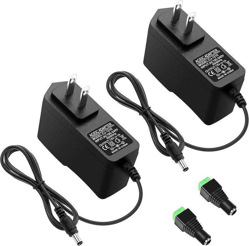
12-Volt Power Module
This power supply is used to power the LED's.
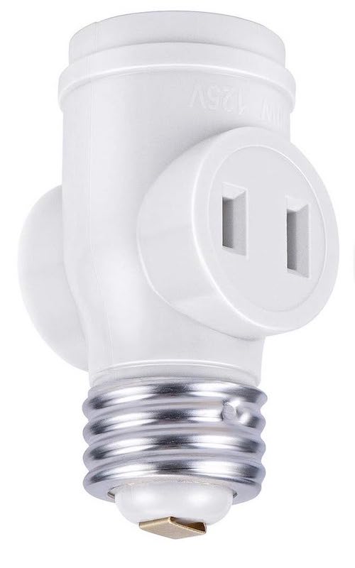
Light Socket Adapter
The 5V power supply that triggers the ESP32 from Deep Sleep is attached to this socket. When the light turns ON this sends 5V to the voltage-divider which in-turn sends 3.3V to GPIO#33 triggering the microcontroller from it from its Deep Sleep state.
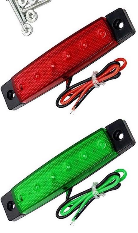
Red and Green LED'S
I used two of each as seen in the images above. I searched for a funky traffic stop light with LED's but failed to find an appropriate one. Whatever that means.
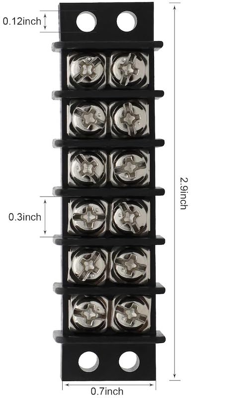
Terminal Block
This was used inside of the enclosure to keep the wiring as tidy as possible.
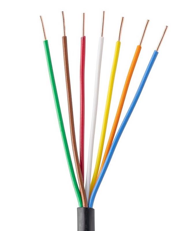
7-strand Solid-core Cable
I only needed six (6) wires for this project but all I could find was this 7-strand variety.
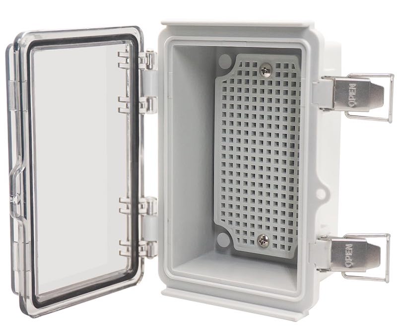
Enclosure
There are a LOT of enclosure's to choose from on the internet. I had used this particular brand on another project and was impressed with its construction. This particular enclosure was re-cycled from another project and its interior dimensions served this project very well.
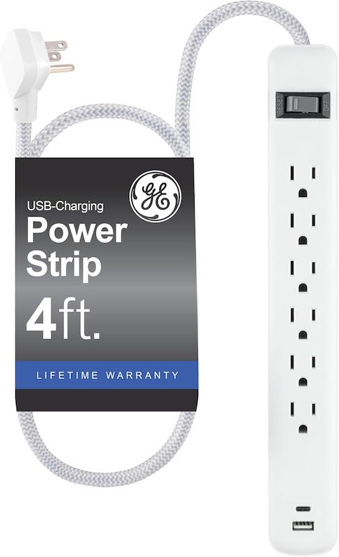
Power Strip
This was used above the garage opener to provide power all of the power supply modules.